
Define a variable buttonState to restore the state of the button.Ĭode Analysis 2-2 Set the input and output status of the pins

Now, press the button, and the LED on the SunFounder Uno board will light up.Ĭonnect the button to pin 12. If "Done uploading" appears at the bottom of the window, it means the sketch has been successfully uploaded. Step 3: Upload the sketch to the Arduino Uno boardĬlick the Upload icon to upload the code to the control board. So we will see the LED lights up and goes out alternately as the button is pressed and released.

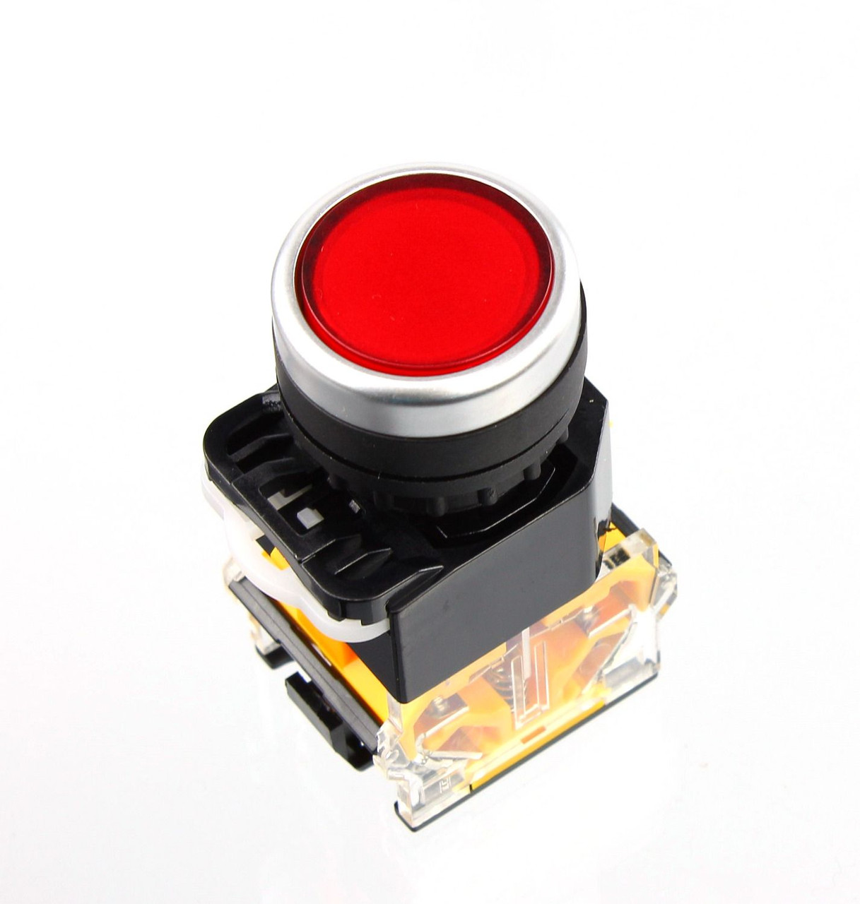
Then release the button (pin 12 changes to LOW) and pin 13 is Low. Set the pin 12 as High level by programming and pin 13 (integrated with an LED) as High at the same time. When the button is pressed, pin 12 is 5V (HIGH). Connect the other end of the resistor to GND and one of the pins at the other end of the button to 5V. Connect one end of the buttons to pin 12 which connects with a pull-down resistor and a 0.1uF (104) capacitor (to eliminate jitter and output a stable level when the button is working).


 0 kommentar(er)
